Views: 34 Author: Site Editor Publish Time: 2025-03-05 Origin: Site


Industrial pressure transmitters convert pressure feedback into pneumatic or electrical signals, enabling remote transmission and control. These devices are particularly advantageous for measuring differential pressure, gauge pressure, vacuum, liquid level, absolute pressure, and specific gravity, offering high accuracy and ease of operation. Additionally, they excel in rangeability and self-diagnosis capabilities.
Various types of industrial pressure transmitters, such as piezoelectric, piezoresistive, and capacitive transmitters, have been developed to meet different functional needs. However, due to harsh operating environments involving high temperatures, high pressures, vibrations, or corrosive fluids, these transmitters may encounter various faults.
Based on application scenarios and internal structure differences, common Industrial pressure transmitters include piezoresistive, piezoelectric, strain gauge, and capacitive types.
Piezoresistive pressure transmitters use a diaphragm with printed resistors. When pressure is applied, a Wheatstone bridge forms, generating a voltage signal proportional to the pressure due to the piezoresistive effect.
Piezoelectric pressure transmitters operate through the conversion of direct and inverse piezoelectric effects.
Strain gauge pressure transmitters are widely used. They work by altering the resistance of strain gauges when the base material deforms under pressure, causing a change in output voltage.
Capacitive pressure transmitters come in electrical and pneumatic types. Electrical capacitive transmitters convert pressure changes into a DC signal, while pneumatic ones output a pressure-based feedback signal.

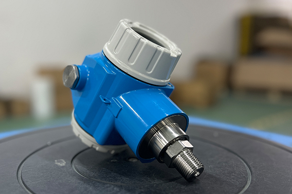
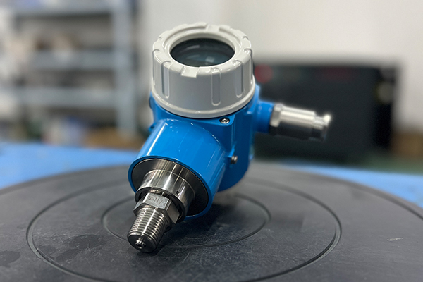
high temperature pressure transmitter

high temp pressure transducer
When an industrial pressure transmitter fails to produce an output, the following checks and tests should be performed:
Confirm that the power supply wiring of the transmitter is correctly connected before powering it on.
Ensure that the transmitter's power supply is a stable 24V DC source.
If using a transmitter with an integrated display, check whether the display is functioning properly. If the display is damaged, replace it before further use.
Apply a 24V DC voltage across the transmitter and use a multimeter to check whether the circuit current is stable and within the normal range.
Regularly verify that the power supply voltage meets the required levels and remains stable.
If the above checks do not resolve the issue, the following corrective actions can be taken:
Reconnect the transmitter’s power supply, ensuring correct polarity.
Verify that the power supply voltage is at least 12V; if it is lower, replace it with a new DC power source.
If the power supply is normal, check whether the current loop is open or disconnected. Confirm that the input resistance in the circuit is ≤ 250Ω.
If replacing the display does not restore normal function, inspect other equipment in the measurement loop for potential malfunctions.
If the transmitter’s output current is ≥ 20mA, it cannot function properly. The following aspects should be checked and tested:
Verify that the power supply voltage is within the normal range.
Check whether the applied pressure exceeds the transmitter’s specified range.
Remove the pressure sensor and inspect it for normal operation, including checking for any damage to the isolation diaphragm.
Inspect the wiring to ensure no loose connections exist.
Confirm that the polarity of the power supply wiring is correct.
Once these checks are completed, the following corrective actions can be taken:
If the power supply voltage is below 12V, check for excessive load resistance in the circuit. Ensure the transmitter’s input impedance meets the condition: (Power Supply Voltage - 12V) / 0.02A Ω.
Reconnect the power supply wiring, ensuring correct polarity.
Replace the transmitter with one that has a higher pressure range, ensuring that its accuracy meets the application’s requirements.
If the pressure sensor is found to be damaged, contact the manufacturer for repair—self-repair is not recommended.
If the transmitter’s output current is ≤ 4mA, it also cannot function properly. The following checks and tests should be performed:
Measure the power supply voltage and check for excessive fluctuations.
Confirm whether the selected transmitter’s range is lower than the actual applied pressure.
Check whether the internal isolation diaphragm of the transmitter is deformed or damaged, leading to sensor failure.
After conducting these checks, the following solutions can be applied:
If the power supply voltage at the transmitter’s load terminal is below 12V, verify that there is no excessive load in the system. Check whether the transmitter’s load input impedance meets the condition: (Power Supply Voltage - 12V) / 0.02A Ω.
Replace the transmitter with one that has a higher range and greater accuracy.
If the pressure sensor is found to be damaged, return it to the manufacturer for repair.
Industrial pressure transmitters are characterized by their simple structure, stable performance, high measurement accuracy, and wide range. To enhance their operational stability and extend their service life, selecting the appropriate model based on the application is essential. Proper maintenance and understanding of common faults and troubleshooting methods will improve the efficiency of pressure transmitters and ensure the normal operation of the system in which they are installed.
About ARTang
ARTang is a global leader in measurement instrumentation, services and solutions for industrial process engineering that energizes the transformation of society and industry to achieve a more productive, sustainable future. We provide process solutions for flow, level, pressure, analytics and digital communications, optimizing processes in terms of economic efficiency, safety & environmental impact.
